Creative Coding for Generative Geometric Art
I recently designed and coded a generative geometric art program that has surpassed my initial expectations as to the nature and variety of the abstract geometric art I would be able to create when using it. I'd like to share with you this adventure in creative coding and the evolution of this generative art program. To that end, this article is written primarily for those who have an interest in the creative coding aspects of generative art and my own software development process.
In this case, I am using the Processing creative coding framework. I particularly like the Processing framework because of its flexibility, its large collection of supplemental libraries, its access to Java libraries, its multiple modes of operation, and the fact that it is available for both Windows and Linux systems. While the Processing framework began as a framework for operating in the Java programming language environment, it has since expanded to both the Javascript and Python programming environments. The Javascript version, P5.JS, seems to have become the dominant version because of its use of Javascript and its ability to run within web pages.
What Is Geometric Art?
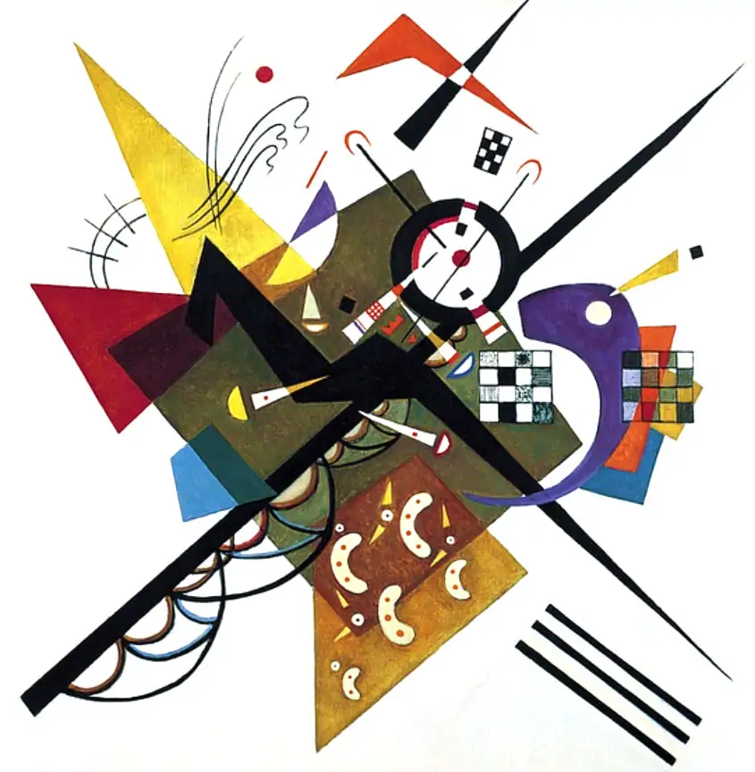
For the art that I create, geometric art is that form of abstract art wherein mathematical shapes or geometric forms like triangles, ellipses, circles, polygons, rectangles, etc. as recognized by boundary defining lines are responsible for the structure of the artwork. This form of art is also referred to as Geometric Abstraction. For additional background, see the Wikipedia entry for Geometric abstraction.
With abstract geometric art, I am particularly attracted to repeating patterns, the visual rhythm, and strong sense of embedded shapes. I also like the futuristic aspects of several subcategories of geometric art. Note that these subcategories are of my own definition and revolve around the nature of the shapes as defined by bounding lines used to define the shapes in the artwork. In the case of the futuristic appearance, I am thinking in terms of those artworks that are structured in such a way so as to suggest a futuristic cityscape.
What Is Generative Art?
Generative art is a product of creative coding whereby a program is written for the express purpose of assisting the artist in producing creative output, whether that output is an image, an audio file, a video, or a poem. A simple definition of generative art is that of art created by a computer program in which the program itself has some predefined degree of control and range of freedom over the art being created, working in conjunction with real time input from either the artist or some stream of incoming data.
When it comes to algorithmic art, the term algorist is used to describe an artist who creates algorithmic art - but only if they are also responsible for creating the algorithm or program being used. For example, if I use a program to create algorithmic art but someone else was responsible for creating that program, I can not claim to be an algorist. So what about generative art? For my part, I lay claim to the title of Generativist - with my definition of generativist being a person who creates generative art and who has also created the algorithm and generative art software being used in the creation process.
Generative AI Art is Not Generative Art
Once upon a time, the words generative art had one meaning - that being art created by a digital artist working in conjunction with a graphics program that had a degree of autonomy in the creative process.
And then along comes Generative AI. Now if you do an image search on generative art, you will see art that was created by a Generative AI in response to a text prompt furnished by a user. This is an entirely different form of digital art creation than that of generative art. Now I do not begrudge people who choose to use generative AI tools to create art, images, stories, poems, etc. In fact, I have taught two workshops on the subject as I find the technology fascinating. Earlier this year I wrote AI Generated Art - The Story Behind The Alien Biomech Portrait about my own experience with using a Generative AI to create a work of digital art.
Now I do get annoyed at people who want to shut the technology down because they view it as a threat to their income. Just imagine where we would be if the typewriter industry had their way and got computers banned because computers were a threat to their income. My concern is with the confusion the public may have by thinking that the term generative art simply means art created by a generative AI and not understand that generative art is one thing and generative AI art is an entirely different thing. Enough digressing. Time to get back on track.
Starting With a Visual Concept
Every program starts with a problem to be solved. As the purpose of this program was to create visual art, this creative coding story began with a visual concept. The idea I had was to write a program that would create artworks that consisted of multiple intersecting and overlapping planes or geometric shapes that would consist of a variety of colors. I've written a number of similar programs before, some favorites of mine being several spirograph and harmonograph programs for which I subsequently developed a class as a way of introducing people to the world of Processing and creative coding. For more about that class/presentation, see Creating Digital Spirographs and Harmonographs with Processing. Once I had a reasonably firm mental grasp on what I wanted the artworks to look like, it was time to sit down and think about how I would implement my vision in code.
Deciding on a Program Design Strategy
In the world of software design, a key challenge is that of problem decomposition. This is the process by which the problem to be solved, in this case the creation of a program for producing generative geometric art, is analyzed, broken down into its component parts, and translated into program code.
When it comes to designing a program, whether for the creation of art or the analysis of data, or the creation of a system simulation, my approach is to begin with the most basic implementation possible. I do not try to code the final solution from the start. Instead, using the process of problem decomposition, I begin by coding the most basic implementation possible. The benefits of this approach are that:
- a simple system can be coded more quickly
- a simple program is easier to debug
- with a simple system, its easier to explore and understand the parameter space
- a simple program is quicker to first viable product, in this case art output
- potential program structure issues are identified more quickly
- a simple program is easier to modify and add new features to
I want to stress the value of minimizing the time to the creation of your first viable art output with any generative art system. The best form of feedback that you can get with any generative art program is the art output it produces. This can quickly reveal how well the program is doing with respect to bringing your visual concept to life. It can also serve to lead you in new, unanticipated creative directions.
For this initial version of the program, I decided that a single system composed of multiple, like shapes would be most easily implemented. This allowed me to focus on identifying what parameters I would use and what their range of values would be. For this program, there were four categories of parameters I would be using:
- parameters that would define a single shape system
- parameters that defined the individual geometric shapes within the shape system
- parameters that defined the field of view and horizon line
- parameters that would allow me to interact with the drawing as the program was running
When it comes to parameters, it is important to not only understand the range of possible values for every parameter you have but also to understand how individual parameters interact with one another as their values change. The collection of parameters you've defined and the range of values for each parameter is collectively known as your program's parameter space.
In terms of implementing my vision, the first major algorithmic hurdle was to identify the methodology or algorithm I would use to assign x,y coordinates to the vertices of the individual shapes. What would the distance be between individual vertices of a single shape? How closely packed would the individual shapes be? Would the shapes be conjoined in some manner or would they be at some distance from one another? How would the shapes be oriented with respect to one another? This is where having a strong visual concept comes into play as knowing what you want to achieve visually will provide you with the answers you need.
2D Simulation of 3D Space
Another decision I had to make was whether or not I would implement this shape system in a 2D space or a 3D space. I could have simulated the 3D space while using a 2D renderer. For example, a 3D camera zoom is really not all that different from a simple 2D shrink/grow distance modification made to the individual vertices. Likewise, Processing provides a rotate() function which can serve as a primitive implementation of a camera tilt effect.
It is with the third dimension plane, Z, that things get tricky. If all of an object's vertices have the same Z value, they are all at the same planar distance from the camera so that a simple shrink/grow trick will work fine. For objects with different Z values, a stacked drawing order can be used to simulate distance by drawing the most distant objects first and then working forward. But this approach requires that all vertices of a shape object lie on the same Z plane. This would make for a 'flat' work of art in that shapes would not be able to intersect with one another in the Z dimension - a visual effect that I did want to be present in the artwork. So what about when an object's vertices have different Z values - meaning that an object's individual vertices are at different planar distances from the camera?
While writing a bunch of code to quasi-simulate a 3D environment within a 2D renderer could work, this would add a lot of complexity and a lot of math to the program and consequently would require a much greater amount of development and programming time to complete. In the interest of time, efficiency, and simplicity, it is simply better and smarter to just use Processing's built in 3D renderer and 3D functions.
As a part of the software development process, instead of adding 3D in the initial version of the program, I choose to limit myself to the 2D environment as this would simplify the initial round of coding and quickly allow me to begin validating my visual concept.
Good Creative Coding Practices
There are several habits that I have when it comes to programming in general and creative coding in particular. These habits have been formed over a lifetime of software engineering. Having at this point conceptualized the visual problem to be solved, my first step is to begin identifying the data structures and variables that I will need to use (and giving them meaningful names). I also identify the general program control structure and any functions that would be needed within that structure.
The Case for Functions
A function can be described as a block of code that has a name, that accepts parameters, performs a single task, and returns an answer or value. Functions are also sometimes referred to as procedures, methods, subroutines, or modules. The instances in which I create and use functions instead of just using inline code are:
- when the same functionality is used in more than one location and more than one time in the program
- when a block of code that has a specific purpose makes the containing control structure less readable, less maintainable, or less understandable
- when I anticipate that I can reuse that block of code in other programs.
For more about functions and their history, read the Wikipedia article on Function (computer programming)
An Example of Initial Geometric Art Creations
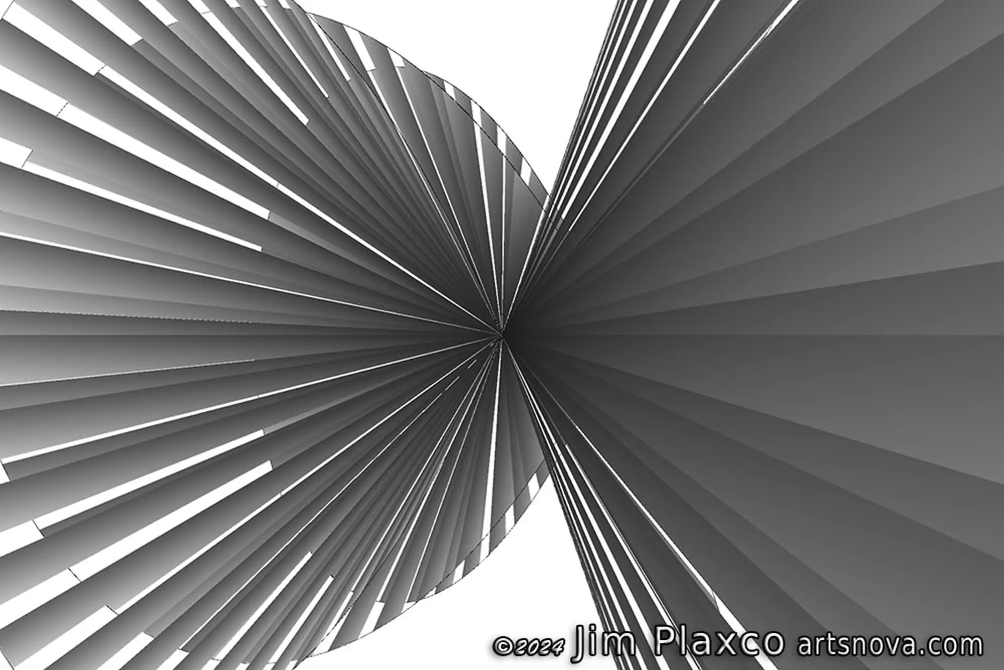
I view getting to output as early as possible in the program development phase as being quite useful as it is the program's output that provides the most tangible feedback into continued development. Image 1 below is the first complete image I created with this program.
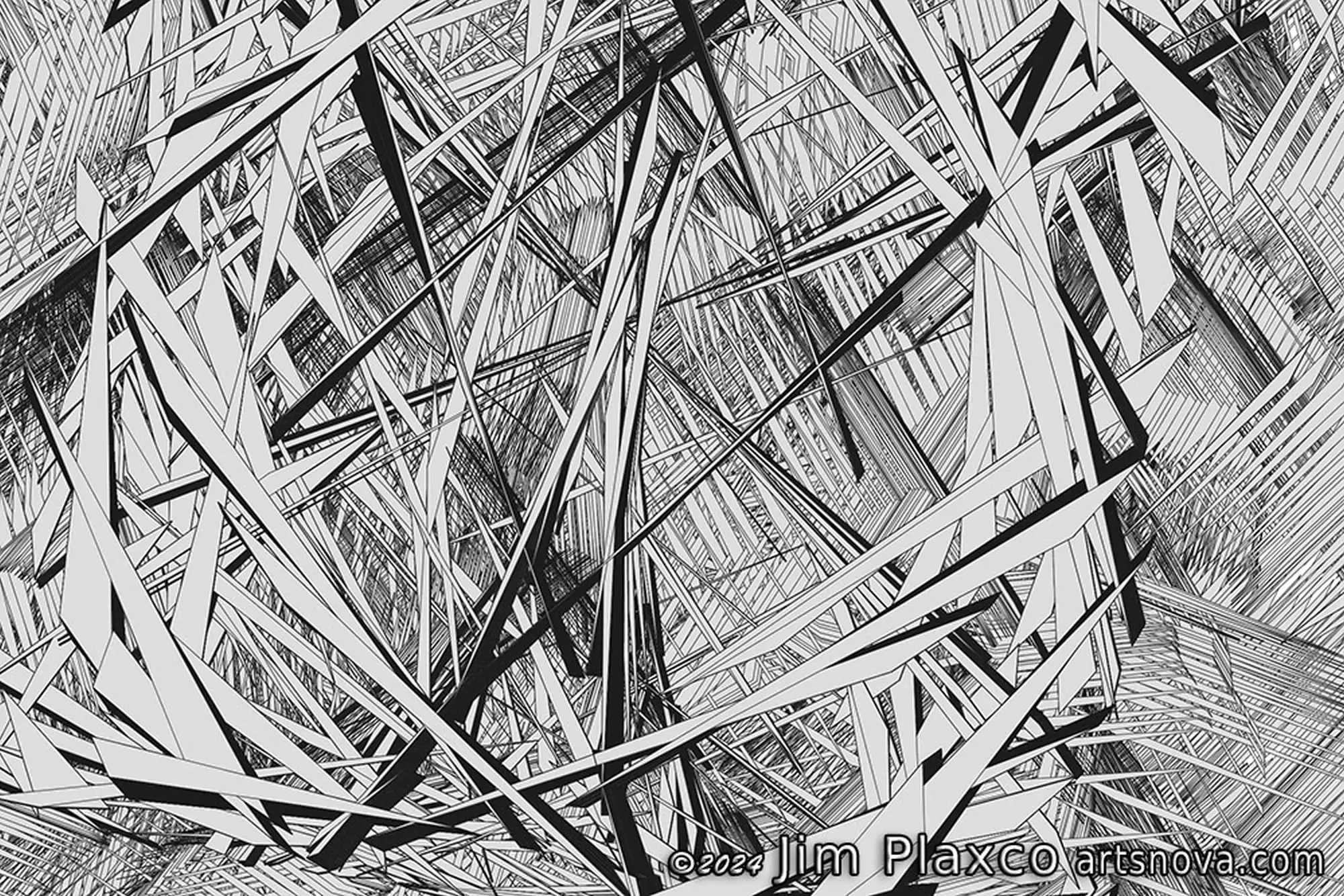
Image 2 below is a second image I created. Note how different it appears than Image 1 above.
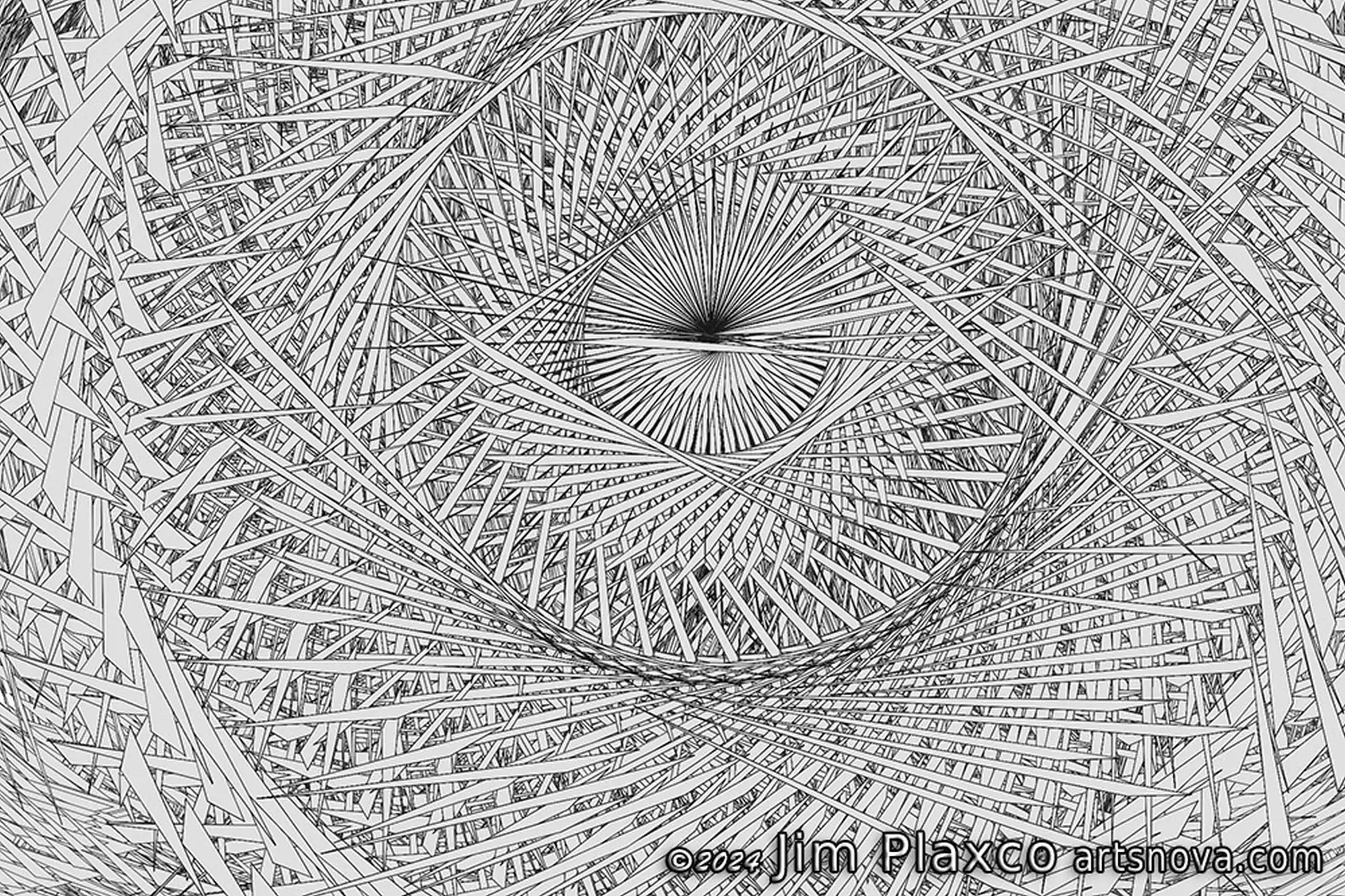
There is no difference in the program code between Image 1 and Image 2. It's just that in each case I used the control options (parameters) I had built into the program to allow me to use my mouse and keyboard to direct the progress of the drawing. And the directions I provided were meant to produce two very different artworks.
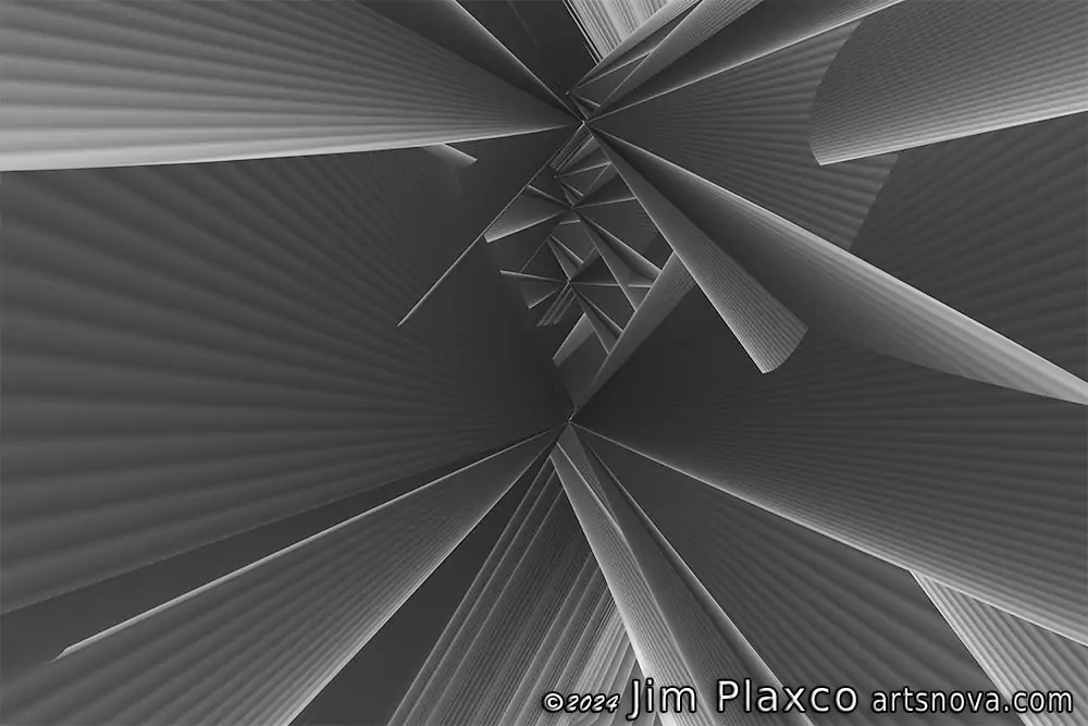
The Next Stage of Program Development: Making it 3D
Satisfied with what I had achieved, it was time to take the next step. This step was to migrate from a 2D system to a 3D system. This update did not result in any fundamental change to the existing program control structure. In fact, adding the third 'Z' dimension was a fairly trivial task. The main challenge of the transition from 2D to 3D was to add code that supported my ability to control the location and pointing direction of the Processing camera object that was now introduced into the system (yes, more parameters). Following is an example of an artwork created by this iteration of the program.
Refactoring the Program to Use Object Oriented Programming (OOP) Classes
The program I had created at this point relied on arrays for storing all the data and using for loops in the main control loop to cycle through the arrays and the data they held. This approach was fine as long as my population of different types of arrays (read variables or parameters) and control options was small. But what I wanted was a program that could easily have its capabilities expanded. So it was at this point that I decided to refactor the program so that instead of using arrays, it would use object oriented programming classes. This meant a fair amount of recoding in the short run but this would make it much easier to add features, parameters, and more shapes in the long run. By recoding my shapes, their vertices, and other characteristics into classes, it becomes a simple copy operation to insert that functionality into other programs.
What Is Refactoring?
Refactoring a program means to rewrite a program's code so that it is either more efficient, more readable, or better structured. Refactoring does not change the program's external behavior - it's just to make the code better. A nice book on the subject of refactoring is Refactoring: Improving the Design of Existing Code by Martin Fowler.
What Is Object Oriented Programming (OOP)?
OOP is an acronym for Object Oriented Programming and represents a programming paradigm that invokes the concept of objects. Object Oriented Programming is a big subject so for now I will just say that it is a methodology for structuring data and functions (aka methods) into classes. Beyond that, the subject is much too large for further discussion here. A quick search on Amazon will reveal a multitude of books on the subject of object oriented programming. One book I have on the subject is Design Patterns: Elements of Reusable Object-Oriented Software by Erich Gamma, et al. Another is Object-Oriented Analysis and Design with Applications by Grady Booch, et al. And there are a multitude of books that are programming language specific with each detailing how object oriented programming is structured within that language's environment.
In order to give you a peek behind the curtains, following is the Processing program code that implements the shape system by using an OOP Class. For simplicity's sake, I have omitted each function's parameter list and code.
class ShapeSystem {
  int points;        // the number of vertices for the object
  int X_focus;       // X center of the system
  int Y_focus;       // Y center of the system
  int Z_focus;       // Z center of the system
  float X_frequency; // Oscillation frequency in the X dimension
  float Y_frequency; // Oscillation frequency in the Y dimension
  float Z_frequency; // Oscillation frequency in the Z dimension
  float X_radians;   // Radian step size for X dimension
  float Y_radians;   // Radian step size for Y dimension
  float Z_radians;   // Radian step size for Z dimension
  float stepSize;    // Step size for setVertices()
  PVector xyz[];     // Vector array for X,Y,Z locations created by setVertices()

  ShapeSystem() {
    // The class constructor is used to assign the initial values to the shape system
    // by using the values in the Parameter List. The constructor then invokes the
    // setVertices() method to build the x,y,z locations array
    }
  void printInfo(int objectID) {
      // This method prints to the console the object's current state.
      // Execution of this method is triggered by a keyboard event.
    }
  void setVertices(){
      // This method determines the X,Y,Z vertex for each shape drawing point
      // Execution of this method is triggered when an instance of this object
      // is created (being called by the ShapeSystem constructor) as well as
      // by the keyboard event that invokes the resetSystem() method
    }
  void resetSystem() {
      // This method resets the system using the values in the Parameter List
      // and rebuilds the x,y,z vector locations array. Execution of this method
      // is triggered by a keyboard event.
    }
}  // end of class definition
Image 4 below is an example of output created by the object oriented version of the program. I will point out that none of the control logic changed and no new parameters were introduced. There are two main benefits at this early stage of refactoring the program so that it uses class objects instead of arrays. First, doing the conversion while the program is still relatively simple is an easier task than doing it later when the program has grown more complex. Second, it is easier to experiment with different parameter values - instead of having to individually change the size and values for multiple arrays. While refactoring the program to implement an object oriented programming solution involves extra work, in the long run it will result in a net saving in programming time as the program acquires additional capability and complexity.
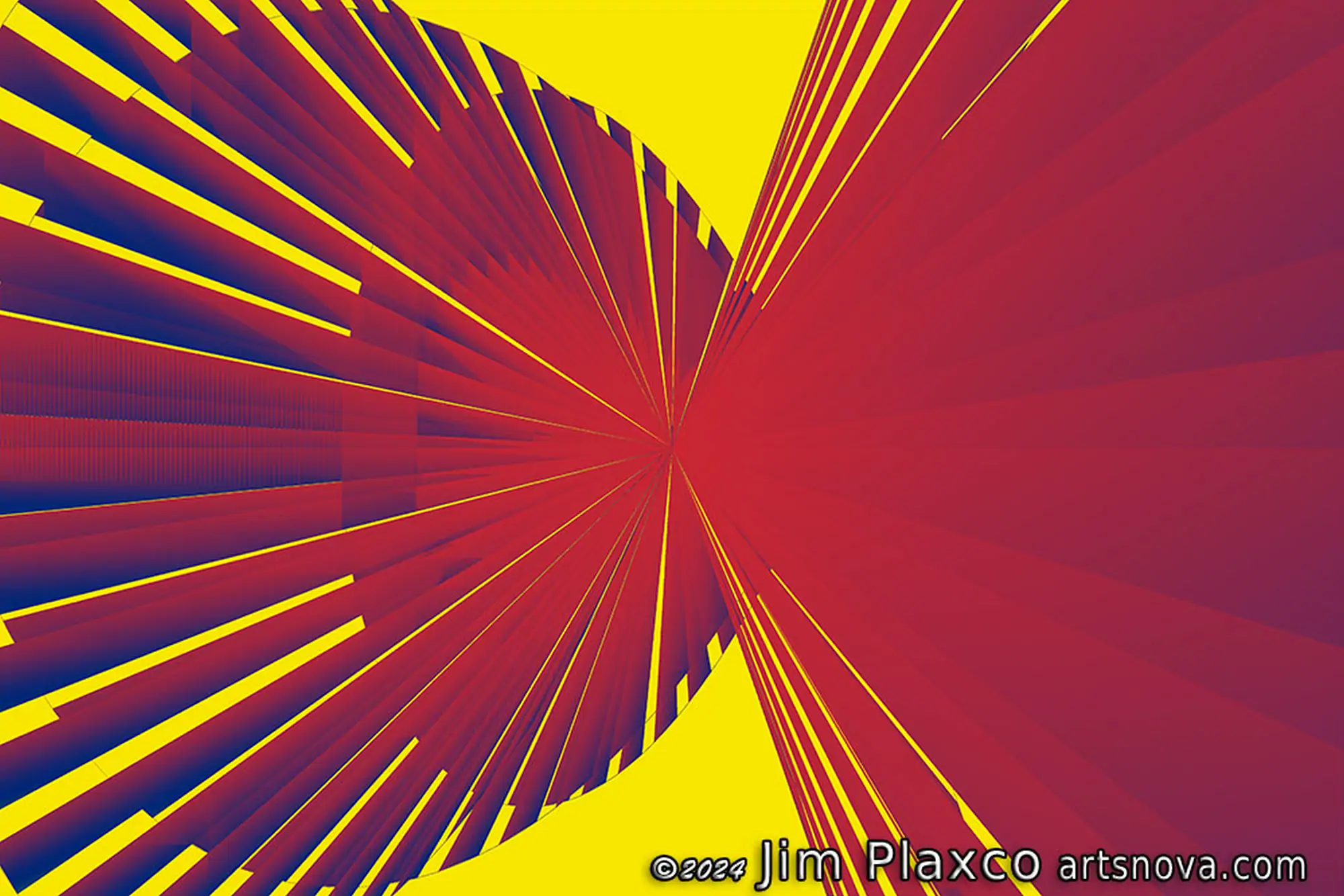
Adding Color
You will note that so far all the generated artworks have been black and white images. It is certainly possible to colorize the images once they've been created. To colorize a black and white image, I use either Adobe Photoshop or Darktable or Rawtherapee's Film Simulation tool and the custom color lookup tables I created. Of the three tools, I'd say that Photoshop is my favorite, followed by Rawtherapee in second place, with Darktable being third.
In the case of Image 3 shown above, I used Adobe Photoshop to create the colorized version of the artwork shown in Image 5 below.
But Photoshop, Rawtherapee, and Darktable are all post-processing options. I would like to see what I can do so that the program itself colors the image in real time. There are any number of ways to go about determining what color should be used for any given shape. Some of the options for determining color could be shape size, shape vertices, a shape's location on the Z axis (distance from the camera), the shape's position in the drawing order, or a fixed color assigned to each shape object. Typically when using some algorithmic formula to assign a color to an object, you will get better results if you are working in the HSV (Hue, Saturation, Value) color space rather than the default RGB (Red, Green, Blue) color space.
Another color assignment option that occurred to me was to use an input image as a color source and pull colors from that image based on the X,Y values of a shape's vertices. Fortunately I already had a function available to accept input coordinates and return the color at those coordinates in a source image. The Processing language code for this function is shown below.
// A function for Processing that returns the RGB color at the
// specified X,Y location.
// This function assumes that a source image has been preloaded
// into the Image object named img and that the X,Y values have
// been appropriately scaled.
color getColor(int x, int y, int inset) {
  // use an inset to avoid pulling colors from the very edge
  if(x < inset) x = inset;
  else if (x > img.width-inset) x = img.width-inset;
  if(y < inset) y = inset;
  else if (y > img.height-inset) y = img.height-inset;
  int pos = (y * img.width) + x;
  return color((img.pixels[pos] >> 16 & 0xFF),
               (img.pixels[pos] >>  8 & 0xFF),
               (img.pixels[pos] & 0xFF));
}
As an aside, if you create a work generative art with some palette of colors and you later decide that those colors need tweaking or replacement, you can always turn to your favorite image editing software to replace those colors.
Examples of Generative Geometric Art
Over the course of developing the generative geometric art program discussed here, I wound up creating a number of variant programs. In fact there are at this time 10 different base programs, each of which has had more than one child variant version created. At the time I am writing this, I have used these programs to create over 100 works of geometric art as a part of the experimentation and learning process. Of those artworks, the following are those that I have made publicly available here on Artsnova as of the time of publishing this article.


Custom Original Geometric Artwork Commissions Available
If you like the artwork you see here, I can create an original work of geometric art for you based on a 3D journey we take together through geometric space. This would be done via a one-on-one online meeting. For details, contact me.
Conclusion
I will conclude by pointing out that all coding is an act of creativity. It is all about the programmer identifying a solution to a problem, designing their vision of the best solution to that problem, and writing the code to implement that solution. For me, what makes creative coding unique is that there is no single, right answer to the problem. Personally, the pleasure of creating generative art lies not just with the creation of the actual artwork, but with the creation of the generative art program that I use to create that artwork.
Software Design References
Following is a list of books on the topic of software design and object oriented programming that you will find useful in whatever creative coding adventures you pursue.
- A Philosophy of Software Design by John Ousterhout
- Refactoring: Improving the Design of Existing Code by Martin Fowler
- Design Patterns: Elements of Reusable Object-Oriented Software by Erich Gamma, et al
- Object-Oriented Analysis and Design with Applications by Grady Booch, et al